

Concrete Column Repair Starts With a Safe, Targeted Plan
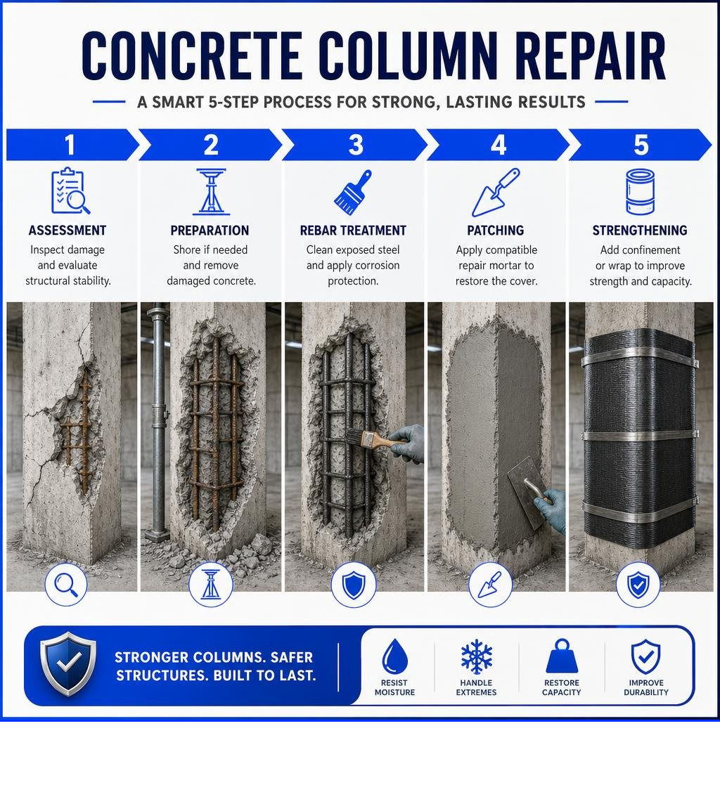
Concrete column repair begins with finding the cause of damage, confirming the column is stable, and choosing a repair that restores both the concrete cover and the column’s load-carrying ability. For spalling or exposed rebar, the usual process is:
- Have a qualified professional inspect cracks, loose concrete, rusted reinforcement, and possible load loss.
- Shore the structure if needed before removing damaged concrete.
- Remove unsound concrete, clean and protect exposed steel, then place a compatible low-shrinkage repair mortar.
- Use a strengthening system, such as a steel jacket or carbon fiber wrap, when the column needs added confinement or seismic capacity.
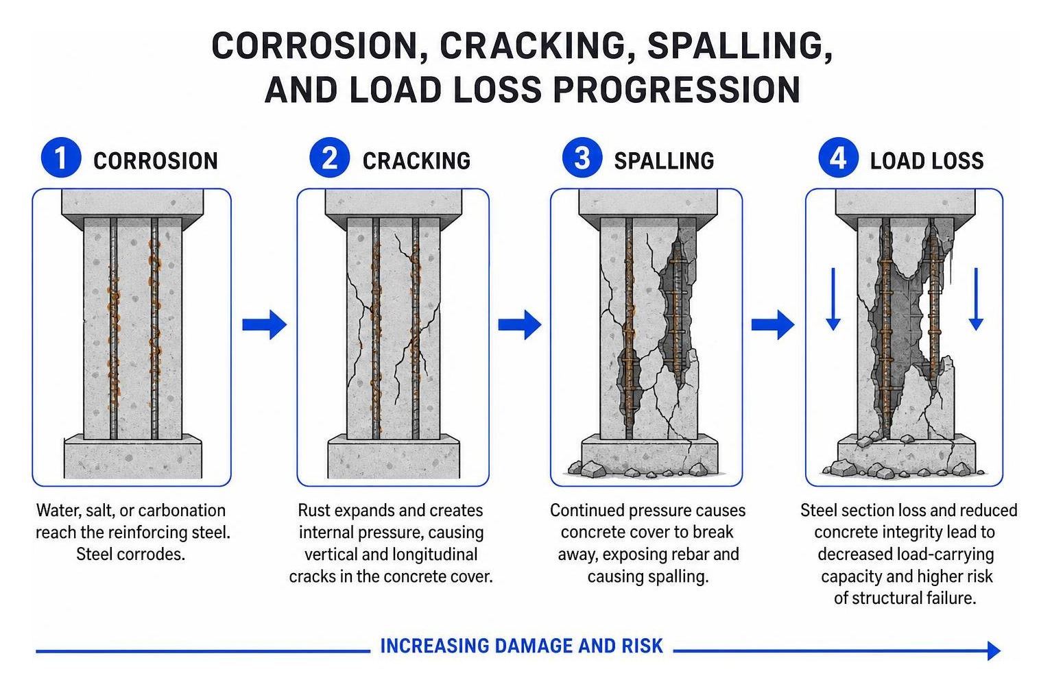
Columns deteriorate when water, salt, freeze-thaw cycles, impact, or carbonation reach the reinforcing steel. Rust expands, cracks the surrounding concrete, and can eventually cause spalling. A cosmetic patch may hide the damage, but it will not solve active corrosion or a loss of structural capacity.
For a load-bearing column, do not start chipping concrete without an engineering review. The repair plan may need temporary shoring, a capacity check, and materials specified under standards such as ACI 562 and ICRI surface-preparation guidance.
I am Trey McNamee, owner of FoamWorks Concrete Leveling, with more than two decades of experience in marketing, strategy, and product development in the building-materials field. At FoamWorks, we bring that practical, quality-focused perspective to concrete column repair questions and the related concrete, foundation, and leveling concerns property owners face.
Simple concrete column repair glossary:
Why Concrete Columns Deteriorate and How to Assess Damage
Concrete columns carry the vertical loads of an entire structure down to the foundation. When they show signs of distress, understanding the root cause is critical to preventing catastrophic failure.
Reinforcement corrosion is the primary culprit behind column failure. In our region—spanning Northwest Ohio, Southeast Michigan, and Northeast Indiana—columns face intense seasonal shifts. Road salts and deicers brought into parking structures introduce chloride ions, while atmospheric carbon dioxide lowers the natural alkaline pH of concrete. Both mechanisms break down the protective passivation layer surrounding embedded steel rebar.
As steel corrodes, it creates rust products that occupy up to six times the volume of the original metal. This internal expansion generates immense tensile pressures (often exceeding 4,000 psi), leading to delamination, vertical cracking, and eventual concrete spalling. In aggressive environments, individual longitudinal steel bars can suffer mass losses between 21.9% and 25.5%, crippling the column’s structural capacity.
Other major causes of column deterioration include:
- Freeze-Thaw Cycles: Water enters porous concrete, expands upon freezing, and breaks down the cement matrix over successive winters.
- Physical Impact: Forklifts in industrial warehouses or vehicles in parking structures cause immediate mechanical crushing and micro-cracking.
- Foundation Settlement: Uneven soil movement beneath footings introduces unexpected eccentric loads and bending moments, requiring comprehensive foundation repair to stabilize the building’s base.
Assessing the Extent of Column Damage
A proper evaluation determines whether targeted restoration is viable or if full concrete replacement is necessary. Structural engineers and restoration specialists utilize several assessment techniques:
- Visual Inspection: Identifying vertical load-induced cracks, rust staining, spalling boundaries, and exposed steel ties.
- Acoustic Sounding: Tapping the column face with a hammer or dragging chains to detect hollow-sounding delaminations hidden beneath the surface.
- Steel Area Loss Measurement: Sandblasting exposed rebar to measure remaining cross-sectional diameter. A loss exceeding 10% to 15% typically triggers the need for supplemental reinforcement.
- Structural Analysis: Performing an axial load and moment capacity check to verify if the remaining uncorroded core can safely support design loads during the repair phase.
Step-by-Step Concrete Column Repair Process
Restoring a load-bearing column requires a precise, engineered sequence. Simply troweling standard cement into a void will result in shrinkage cracks, debonding, and continued corrosion.
The standard restoration workflow follows strict ICRI (International Concrete Repair Institute) Guideline 310.1R benchmarks:
- Perimeter Saw-Cutting: Saw-cut the repair boundary to a minimum depth of 0.5 inches (12 mm). Cuts must be made perpendicular (90 degrees) to the surface. Feather-edging is strictly avoided to prevent edge spalling.
- Cavity Shaping: Square off the repair zone into simple rectangular shapes, eliminating sharp re-entrant corners that concentrate stress.
- Substrate Profiling: Chip away damaged concrete until reaching sound material, achieving a Concrete Surface Profile (CSP) of 5 to 7 for optimal mechanical interlock.
| Feature / Metric | Standard Concrete Patch | Polymer-Modified Structural Repair Mortar |
|---|---|---|
| Shrinkage Characteristics | High drying shrinkage (prone to cracking) | Low shrinkage / micro-expansion control |
| Bond Strength to Substrate | Low to moderate mechanical bond | High polymer-enhanced adhesion |
| Compressive Strength (1 Hour) | Under 500 psi | 3,000+ psi (rapid structural turnaround) |
| Compressive Strength (28 Days) | 3,000 – 4,000 psi | 7,000+ psi |
| Modulus of Elasticity Match | Variable; often creates stress risers | Engineered to match existing concrete core |
| Application Style | Requires extensive formwork | Form-and-pour or hand-pack overhead/vertical |
Preparation and Shoring for a Concrete Column Repair
Because columns carry active structural loads, removing concrete reduces their cross-sectional area and temporary load-carrying capacity.
Temporary shoring must be installed before chipping begins whenever structural integrity is compromised. Engineers design shoring systems to support 100% of the column’s dead load plus anticipated construction live loads, typically incorporating a 25% to 50% safety contingency.
Once shoring stabilizes the structure, workers chip out unsound concrete using light pneumatic hammers (15-lb to 30-lb maximum to prevent micro-fracturing sound concrete). Concrete must be removed at least 0.75 inches (19 mm) to 1.0 inch behind exposed steel rebar—or 0.25 inches larger than the maximum aggregate size of the repair mortar. This full clearance allows the new mortar to completely encapsulate the steel, locking it into the core.
Executing a Structural Concrete Column Repair with Mortar and Bonding Agents
- Rebar Preparation: Clean all exposed reinforcing steel to a near-white metal finish using abrasive blasting or mechanical wire brushing to eliminate rust and scale. If rebar cross-section loss exceeds structural tolerances, splice in supplemental bars.
- Corrosion Protection: Apply an anti-corrosion barrier coating, such as an active zinc-rich primer or an epoxy-modified cementitious coating (e.g., DURALPREP A.C. applied in two 20-mil coats), directly to the prepared steel.
- Substrate Pre-Wetting: Bring the concrete substrate to a Saturated Surface Dry (SSD) condition, ensuring no standing water remains.
- Mortar Placement: Place a high-performance, low-shrinkage mortar. Specifications like EUCOREPAIR V100 specifications call for fiber-reinforced, polymer-modified mixes formulated for vertical and overhead placement without sagging. In laboratory trials, structural Class R3 cementitious mortars have demonstrated exceptional compatibility, recovering up to 84% of original column stiffness without requiring chemical bonding agents when applied to an SSD substrate.
- Consolidation and Finishing: Hand-pack or form-and-pour the mix, working it thoroughly behind rebar to eliminate air voids. Trowel flat, match the surrounding surface texture, and immediately apply wet curing or an approved curing compound to prevent plastic shrinkage cracking.
Structural Strengthening Techniques: Traditional vs. Advanced Composites
When a column suffers substantial capacity loss or needs to meet updated building codes, localized patching must be paired with external structural strengthening. In homes with support pier issues, stabilizing structural uprights goes hand-in-hand with crawl space repair to address moisture intrusion and wood-to-concrete contact points.
Traditional Jacketing vs. Modern Composite Overlays
- Reinforced Concrete Jacketing: Enclosing the damaged column in a new cage of longitudinal bars and ties, then pouring a 3- to 5-inch concrete ring around it. While effective, it adds substantial dead weight and consumes valuable floor space.
- Steel Jacketing / Caging: Welding structural steel angles and transverse straps around the column. This delivers high lateral confinement but leaves steel susceptible to future corrosion and complicates architectural finishes.
- Fiber-Reinforced Composites: Wrapping columns in high-strength carbon or glass textiles saturated in resin, providing immense confinement with virtually zero added weight or floor space loss.
Carbon Fiber Reinforced Polymer (CFRP) Confinement
Carbon Fiber Reinforced Polymer (CFRP) wrapping has revolutionized structural retrofits. Applied in accordance with ACI 440.2R guidelines, CFRP acts as a high-tensile hoop around the column. As vertical loads compress the concrete core, the column attempts to expand laterally (Poisson’s effect). The rigid CFRP wrap resists this expansion, putting the core under triaxial compression and dramatically increasing its ultimate load-carrying capacity by 25% to 100%.
In a recent study on seismic repair of corroded columns with CFRP shells, severely corroded columns restored with concrete-filled CFRP shells and headed steel bars demonstrated remarkable structural recovery:
- The repaired corroded column achieved a maximum lateral force of 180 kN—1.5 times the strength of an undamaged control specimen (117 kN) and 1.7 times the corroded column (109 kN).
- The repaired specimen reached a maximum drift ratio of 10.0% (compared to 9.0% for control and 6.0% for corroded columns).
- Displacement ductility reached 4.5, while cumulative hysteretic energy dissipation before fracture reached 491 kN-m—2.1 times that of the control and 7.1 times that of the un-repaired corroded column.
- Strain measurements in the CFRP shell reached 4,500 microstrain at 7.0% drift ratio, utilizing 65% of the composite’s ultimate tensile capacity without premature rupture.
Fabric Reinforced Cementitious Matrix (FRCM) and Hybrid Systems
For structures where organic epoxies are undesirable due to high temperatures or vapor permeability concerns, Fabric Reinforced Cementitious Matrix (FRCM) systems—designed per ACI 549.4R—provide an ideal alternative. FRCM utilizes carbon or alkali-resistant glass mesh embedded within an inorganic cementitious mortar matrix.
Recent research on hybrid FRCM strengthening shows that pairing carbon-based FRCM with embedded near-surface-mounted (NSM) glass fiber rods boosts load capacity by 54%, elevates energy dissipation by 155%, increases ductility by 89%, and reduces subsequent re-corrosion rates by approximately 16%.
Further investigation into hybrid FRP and high-strength concrete overlays indicates that combining NSM reinforcement with glass-fiber textile mesh and engineered cementitious composites (ECC) or ultra-high-performance concrete (UHPC) increases axial load capacity by 11% to 78% while boosting energy absorption by up to 382%, effectively preventing brittle column failure.
Long-Term Durability, Building Codes, and Cost Considerations
A durable concrete repair must comply with structural building codes like ACI 562 (Code Requirements for Assessment, Repair, and Rehabilitation of Existing Concrete Structures).
To ensure long-term durability:
- Apply Migrating Corrosion Inhibitors (MCIs): Penetrating amino-alcohol or carboxylate formulations migrate through concrete pores to form a protective monomolecular film over rebar.
- Surface Hydrophobic Treatments: Apply silane or siloxane sealers to block external water and chloride penetration while allowing interior water vapor to escape.
- Sub-Slab and Foundation Stabilization: Columns rely on stable footings. If sub-slab soils settle or wash away, the footing shifts, placing severe torsional stress on columns. Our precision concrete leveling services use high-density polyurethane foam injection to lift settled slabs and stabilize underlying soils. Polyurethane leveling costs 30% to 50% less than full tear-out and replacement, completes in just a few hours with no heavy excavation, and restores solid ground support beneath critical structural components.
Frequently Asked Questions About Concrete Column Restoration
When can a concrete column be repaired versus replaced?
A concrete column can be repaired if reinforcement cross-sectional area loss is under 20% to 25%, the core concrete remains sound, and the column has not suffered severe structural buckling. When rebar loss is extreme, multiple main bars have severed, or extensive concrete crushing spans across the main core, full shoring and column replacement becomes the more safe and cost-effective approach.
How deep should concrete be removed around corroded rebar?
Concrete should be removed to a minimum depth of 0.75 inches (19 mm) to 1.0 inch behind the exposed reinforcing steel, or at least 0.25 inches (6 mm) larger than the coarsest aggregate in the repair mortar. This clearance ensures the new repair material fully encapsulates the bar, creating a continuous mechanical interlock and preventing future corrosion pockets.
How does carbon fiber confinement increase column capacity?
Carbon fiber wraps provide passive lateral confinement. When a column is placed under vertical compression, the concrete expands outward against the rigid, high-tensile CFRP jacket. The jacket exerts inward hoop stress, placing the core under triaxial confinement, which raises ultimate compressive strength by 25% to 100% and substantially improves ductility against seismic or dynamic loads.
Conclusion
Restoring deteriorated columns protects your building’s structural framework, preserves property value, and ensures tenant safety. By following proven engineering standards—from proper shoring and perimeter saw-cutting to advanced repair mortars and carbon fiber wraps—you can restore a compromised column to exceed its original load capacity.
At FoamWorks Concrete Leveling, we bring over 30 years of industry experience, lifetime warranty protection, and dedicated local service to property owners throughout Northwest Ohio, Southeast Michigan, and Northeast Indiana. Whether you need slab stabilization, foundation support, or column evaluation, our family-owned team is here to help. Contact us today for a free estimate and discover how our advanced concrete repair solutions keep your property standing strong.